
Replacing the Z-rod
Part 1: Remove the Old Z-Axis
Step 1: Remove the plastic cover, the vat, and the building plate.
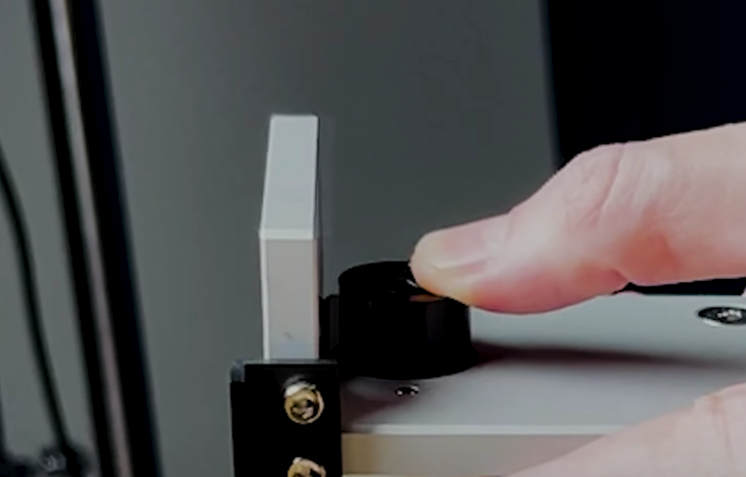
Step 2: Make sure the building plate on the Z-axis has retracted completely. If it hasn’t, click TOOLS, and then click MANUAL; click on 10mm several times to retract it.
Step 3: Turn off the 3D printer and unplug the power cable.
Step 4: Flip the 3D printer and remove the printer’s bottom with an m3 Allen wrench which is included in the toolbox.
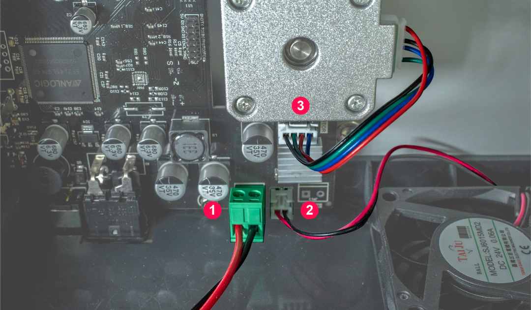
Step 5: Remove the ➊ LED cable and ➌ motor cable from the mainboard.
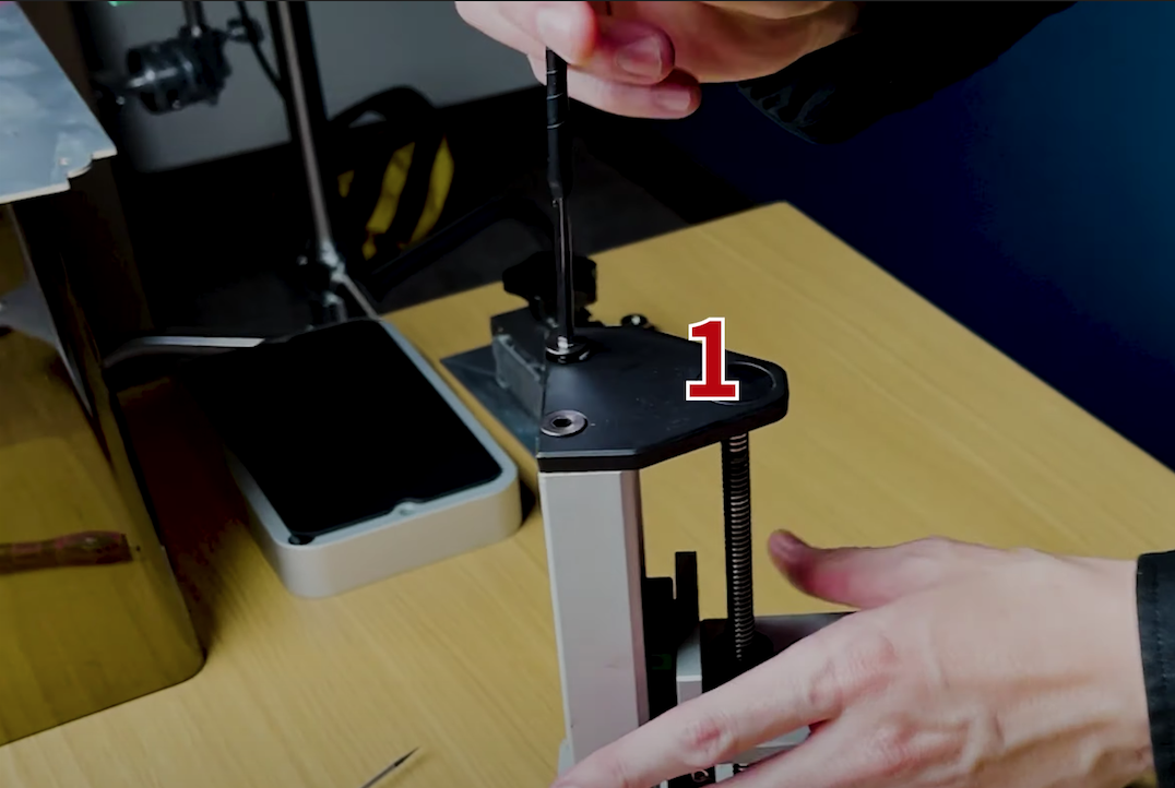
Step 6: Remove the black screws on top of the Z-axis.
Step 7: Tape around the Z-axis and the Z-rod to prevent the linear guide from falling off.
DO NOT remove the linear guide from the rail as it will cause great damage to the Z-rod.
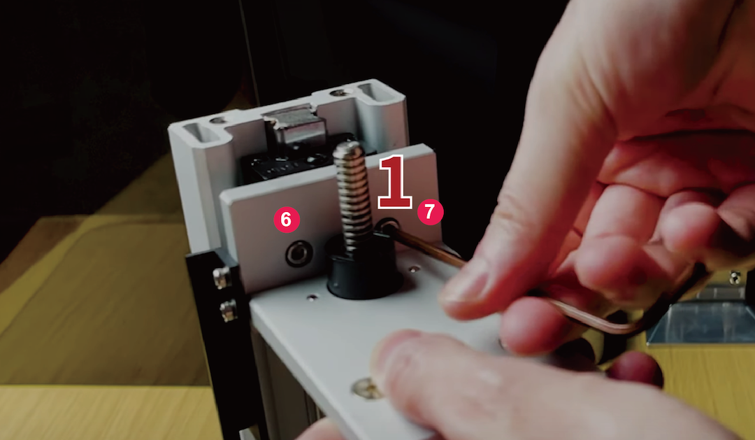
Step 8: Remove the ➏ ➐ two screws holding the T-plate.

Step 9: Turn the Z-rod clockwise and then remove the T-plate. Make sure to press your thumb on the bearing sleeve to prevent the springs from bouncing out.
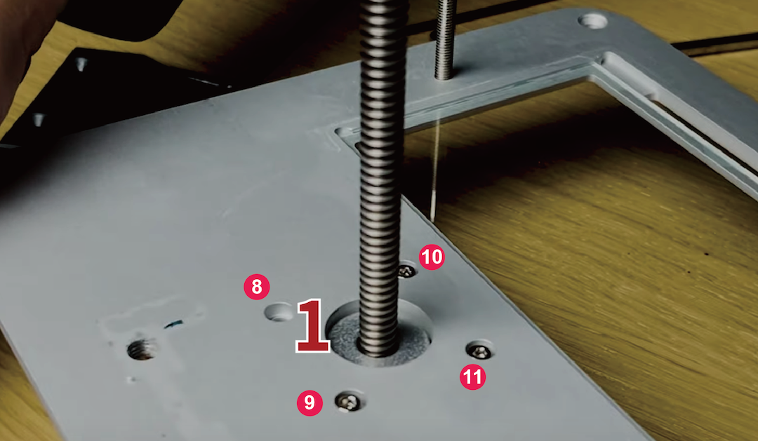
Step 10: Lay it flat to prevent the Z-rod from dropping at a height. Remove the four screws, then remove the Z-rod.
Part 2: Install the New Z-axis:
Step 11: Place the Z-rod back in place and tighten the screws in a cross pattern order.
Step 12: Place the T-plate back onto the Z-rod. Make sure you’ve pressed your thumb against the bearing sleeve while turning the z-rod counterclockwise.
Step 13: Tighten the ➏ ➐ two screws holding the T-plate.
Step 14: Tighten the black screws that are present on top of the resin 3D printer.

Step 15: Reattach the ➊ LED cable and ➌ motor cable.

Step 16: Place the bottom back onto the 3D printer and tighten the screws.
Step 17: Turn the 3D printer upright. Plug in the power cable, and turn the 3D printer on.
Step 18: Perform the LCD test to ensure that the LCD is functioning properly.